Detail of the bow. Additional detail includes guy ropes that are on the real boat, coils of rope, fire hose reels, oil can, bracket for the spare propeller and bracket for the spare anchor.

Here I have added an additional box, tarpaulin and rope.

Showing the tyres, additional detail in the life boat (ropes) and bracket for the spare propeller.

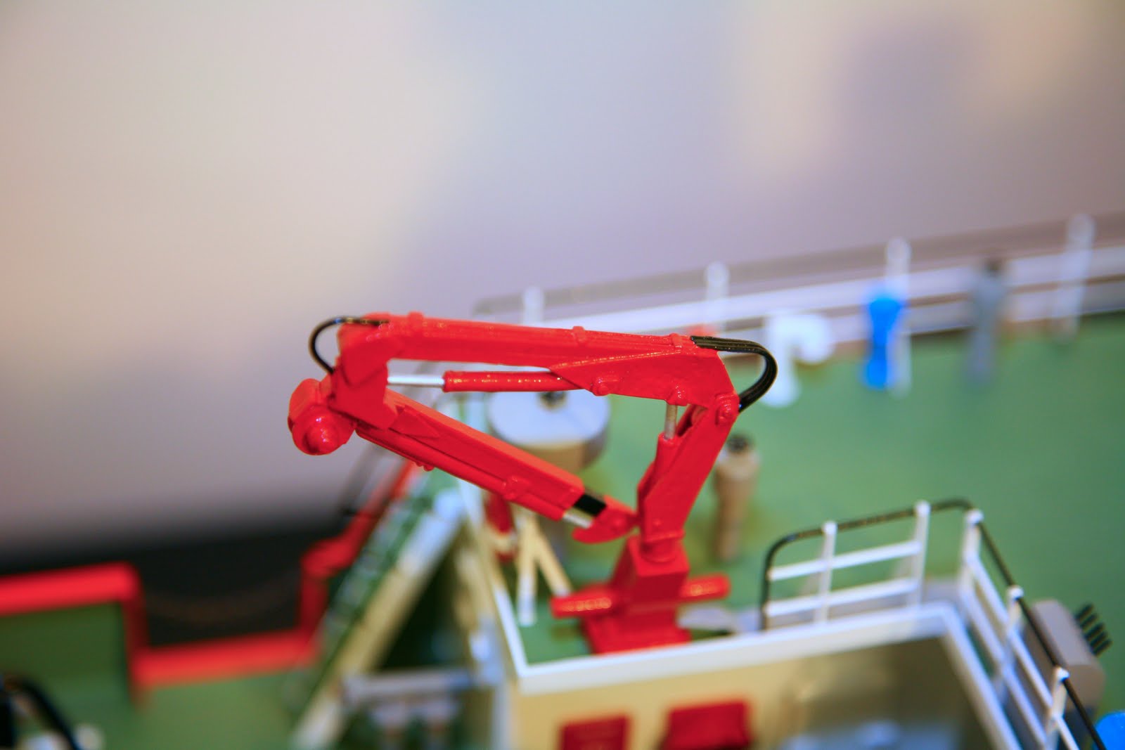
I added hydraulic hose on the crane to add realism.

A view of the winches.

I added a deck full of extras for additional interest.

Additional guy ropes, rigging and flag, as included on the real ship.